Battery-powered hill-climb vehicle
As team lead for a group of five, I took a battery-powered vehicle from concept through calculation, drawings and fabrication to race day in UL's Design, Build, Compete module. The design was driven by one rule: minimise mass, then pick the drivetrain with the numbers.
- Context
- ME4042 Design, Build, Compete, UL
- Role
- Team lead, team of five
- When
- Jan–Apr 2025
- Tools
- SolidWorks, Excel
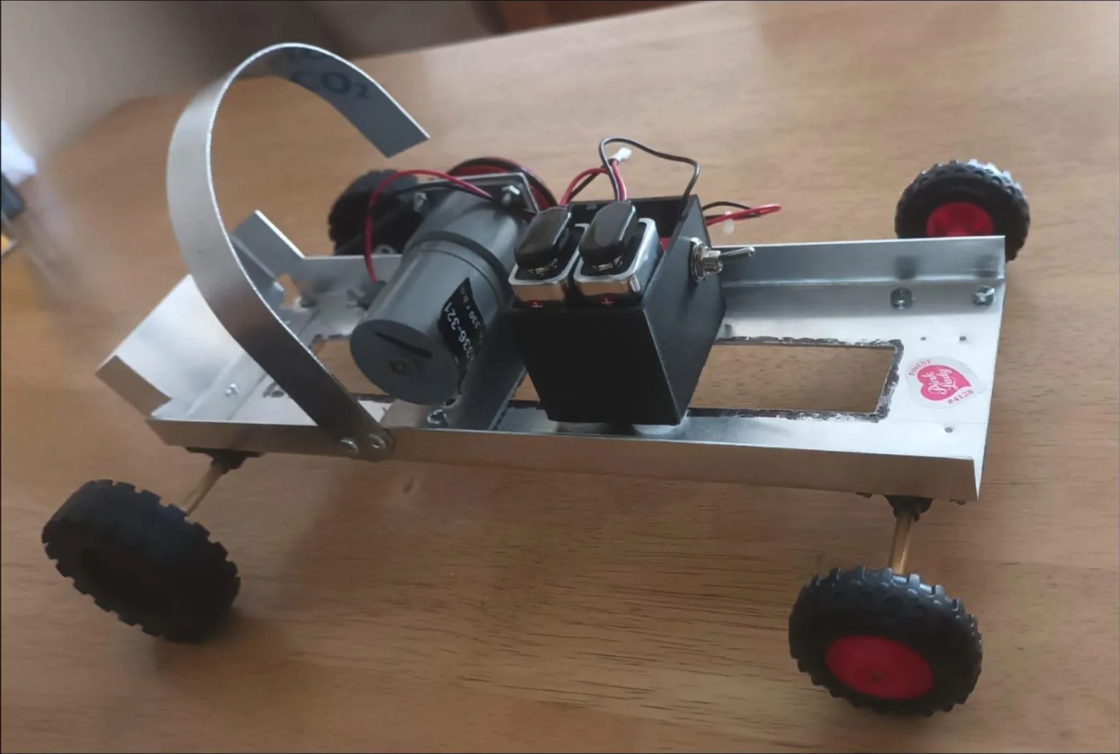
Problem
Build a battery-powered vehicle that climbs a 5° incline carrying a 400 g payload (a water bottle) as fast as possible, within a motor torque limit of 0.025 N·m and a total manufacturing time of 6 hours.
My role
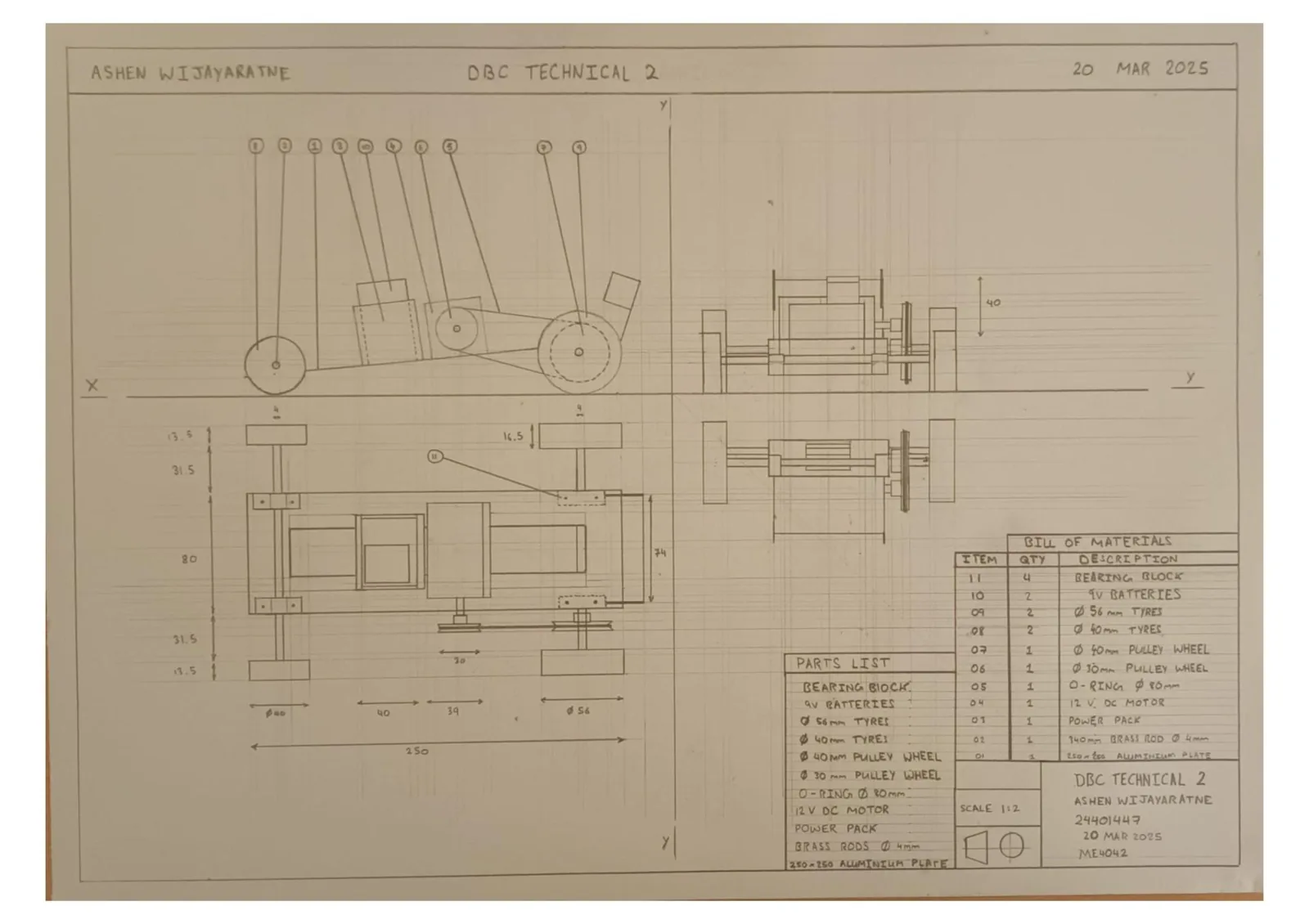
Team lead for a team of five. I led the end-to-end design, optimisation and fabrication of the vehicle, using CAD modelling, technical drawings and analytical optimisation to weigh performance trade-offs and guide design decisions. I managed the project from concept through fabrication and testing, and produced the technical documentation, engineering drawings and performance analysis tools.
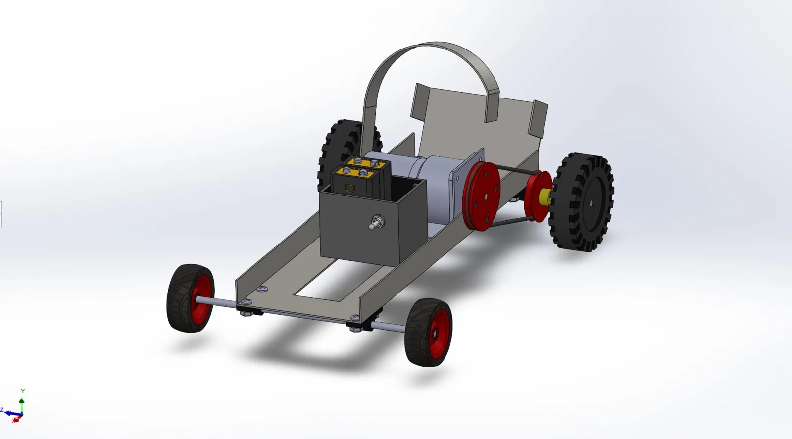
Day to day that meant chairing the meetings, keeping the Gantt chart and the minutes, writing the team contract, and picking up tasks where others fell behind. On the engineering side I built the Excel spreadsheets the team used to settle the pulley ratio and the centre of mass, made the SolidWorks model and render, and the hollow chassis the team used was based on my concept.
The team: Razuk Atik (propulsion calculations), Reza Mohammadi and Oran Murphy (drawings), Aidan Cashin (weight reduction and documentation).
Method
- Merge concepts. Each member designed a vehicle. We kept the strongest parts of each: a rear-mounted bottle stand from Reza's design, larger rear wheels from Razuk's, and my hollow chassis.
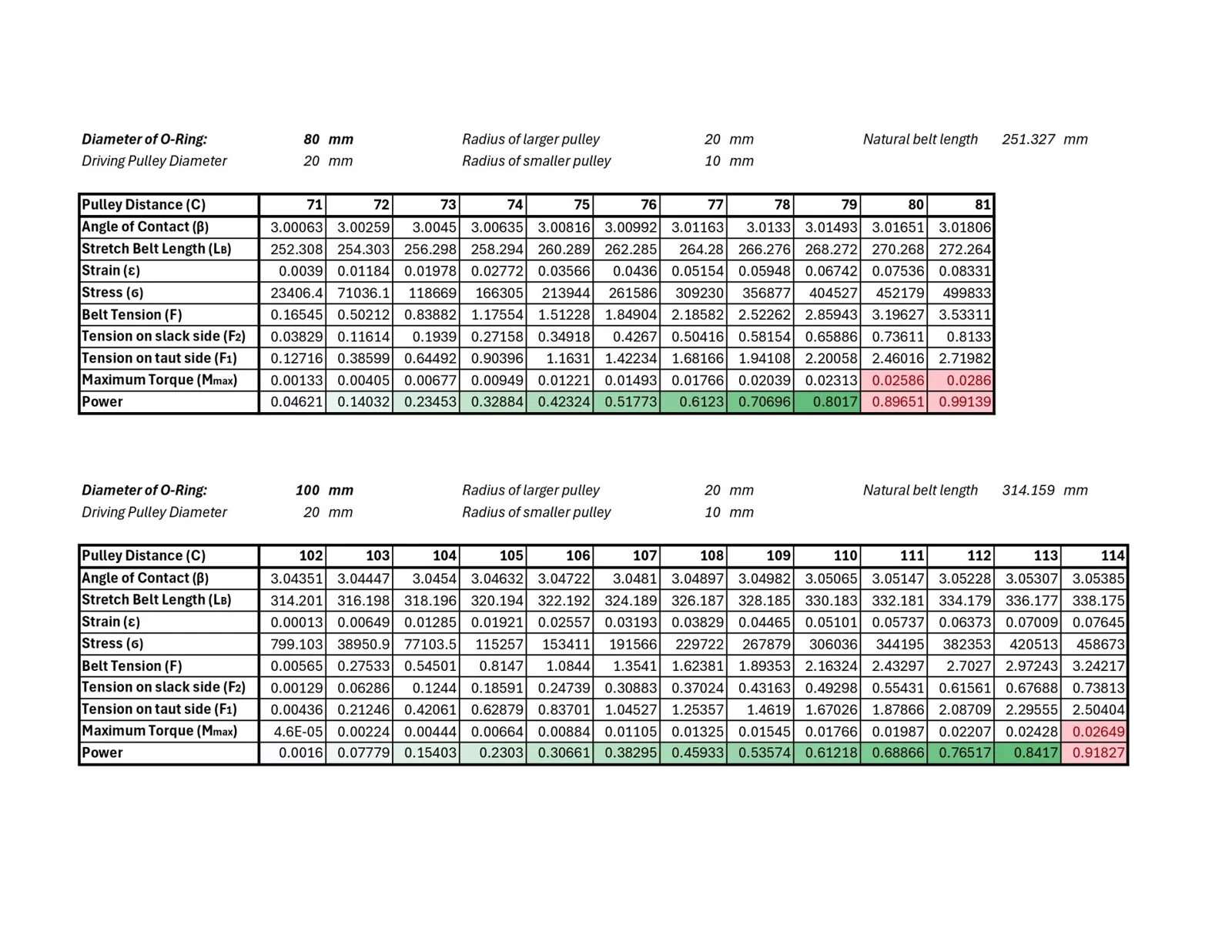
- Drivetrain in Excel. I calculated climb time and motor torque for 20 pulley combinations on 4 wheel arrangements (80 in total) and took the fastest one that stayed under the 0.025 N·m torque limit. That gave a 30 mm motor pulley, a 40 mm axle pulley, 56 mm rear wheels and 40 mm front wheels.
- Belt centre distance. Starting from 71 mm, I increased the distance 1 mm at a time, recalculating belt tension and motor torque, and stopped at 78.8 mm. That kept about a 10% torque margin and moved weight towards the rear.
- Centre of mass. Calculated from every component's mass and position, with the bottle modelled as tilted.
- Build. A 250 × 80 mm aluminium sheet with a 30 × 200 mm hollow section, and the bottle support folded from the offcut. I modelled the car in SolidWorks, and a teammate's Tinkercad model was 3D printed to check the layout before cutting metal.
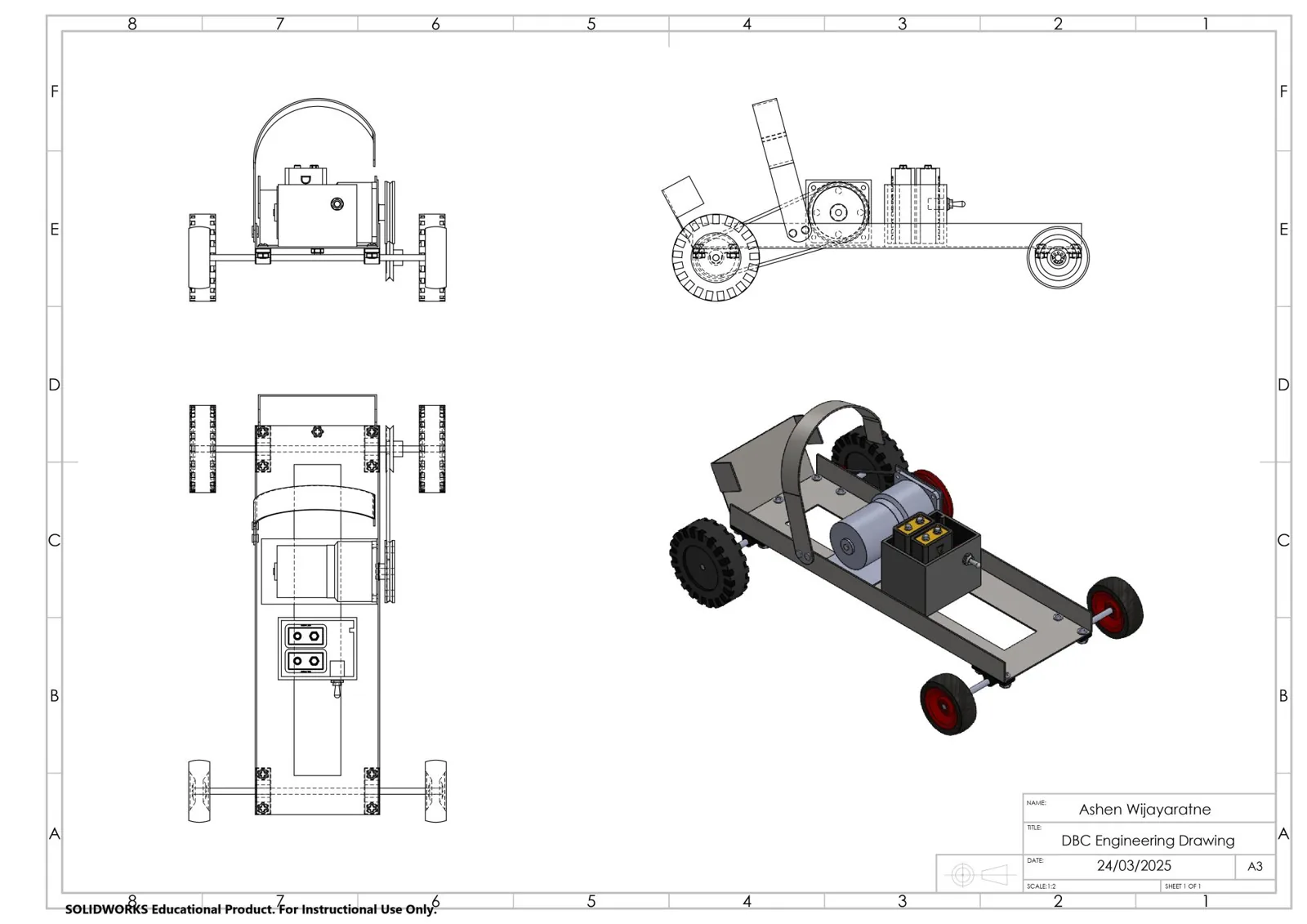
Assumptions
- Rolling resistance of 0.4 N/kg and a power efficiency of 0.85, as given in the brief.
- The belt model came from an online visual calculator plus the Excel tension and torque equations.
- The bottle was modelled as a tapered cylinder tilted at 33° to the ground.
- The target centre of mass, about 65% of the length behind the front axle, came from online research on small model cars.
Result
- Placed
- 11th / 45
- Grade
- A1
- Predicted mass
- 0.75 kg
- Predicted climb
- about 17 s
- The calculated motor torque was 0.0233 N·m, inside the 0.025 N·m limit.
- The centre of mass was 137.1 mm from the front axle, against a 137.5 mm target, so it sat over the rear axle as intended.
- From conversations with other teams, our car was lighter than 10 of them (22.2% of the 45 teams).
Verification
- The centre of mass was checked against the 0.65 length target. It came out within half a millimetre.
- We planned post-build checks: climbing the slope loaded, crosswind stability, and wheel grip on surfaces of different friction, because the race is outdoors.
The design did not change after the report. Only the race position and the grade came afterwards.
What I’d change
I'd delegate more deliberately and set up clearer ways to share the workload from the start, so less of it fell back on the team lead when people fell behind.