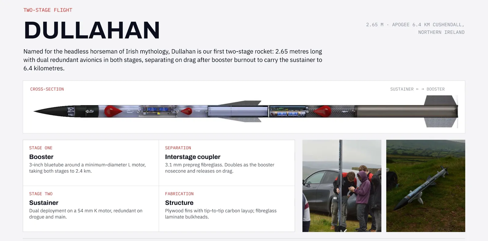
Avionics and payload bays for a two-stage rocket
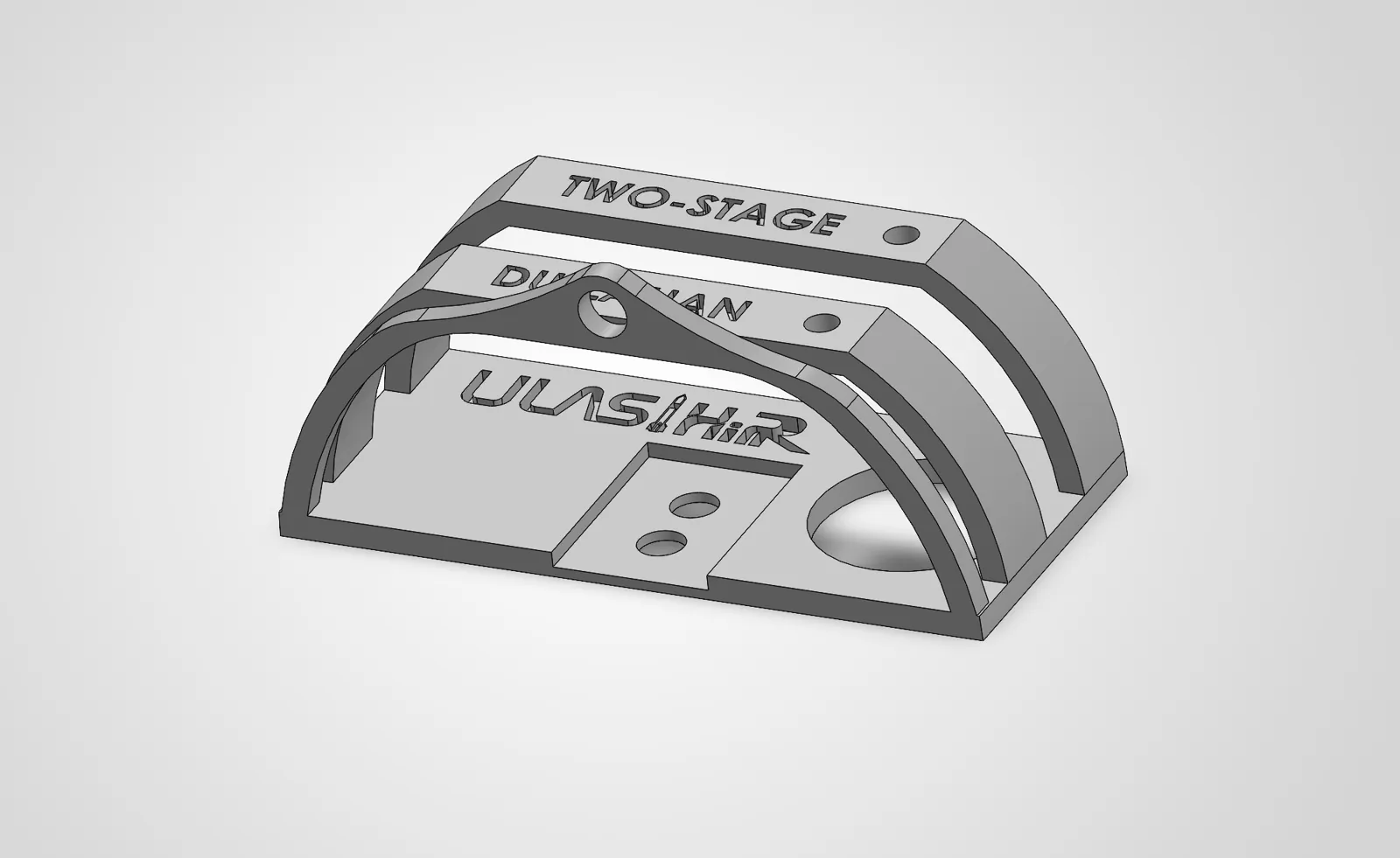
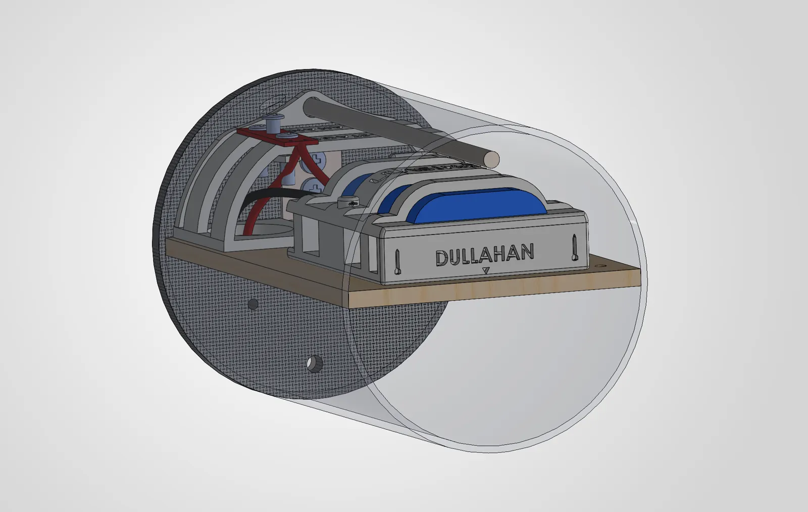
For ULAS HiPR’s Dullahan rocket I designed and built the bays that carry the flight electronics in both stages, taking them from requirements through CAD, structural design and optimisation to parts made in the workshop and integrated in the rocket.
- Team
- ULAS HiPR, University of Limerick
- Role
- Avionics & Structures Design Engineer
- When
- Jan–Aug 2026
- Tools
- SolidWorks, Altair HyperWorks
Problem
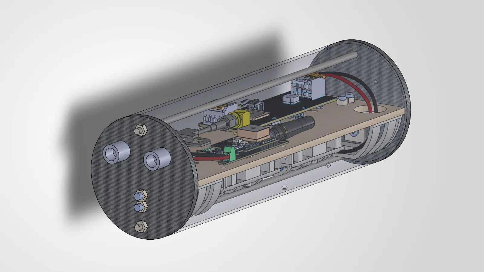
Dullahan is ULAS HiPR’s first two-stage rocket, 2.65 m long, with redundant avionics in both stages. Each stage needed a bay that holds the flight computers, batteries and arming switches securely through launch, staging and recovery, fits inside the airframe, and can be assembled and armed by the team on the day.
My role
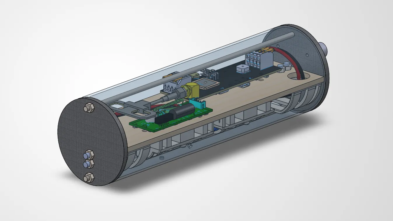
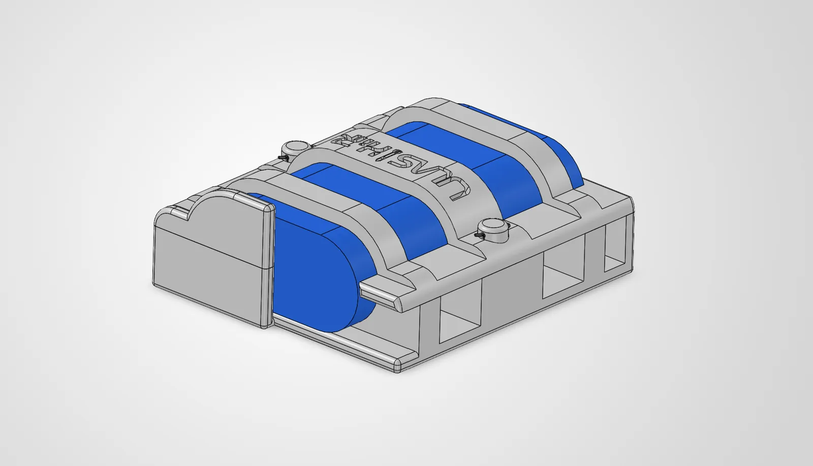
I owned the design of the avionics and payload bays for both stages, from the initial requirements to the manufactured parts. That included the SolidWorks models and engineering drawings for the multi-part assemblies, the topology optimisation of the payload holder and battery cradle, and making the parts in the workshop.
Method
- Requirements. Worked out what each bay had to hold, how it attached to the airframe, and how the team would get at the switches and wiring.
- CAD and drawings. Modelled the bays and their custom parts in SolidWorks, with drawings that considered integration, GD&T, tolerancing, design for manufacture and assembly.
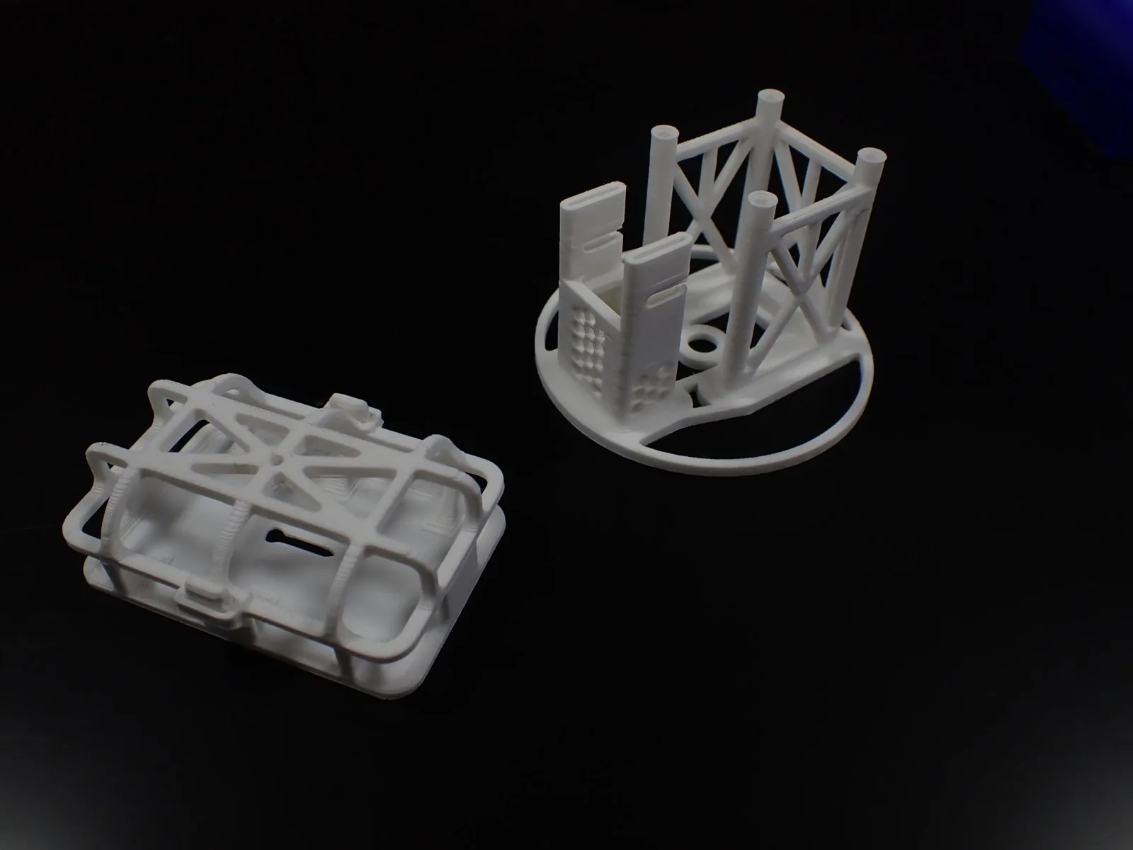
- Topology optimisation. Used Altair HyperWorks to take material out of the payload holder and battery cradle while keeping the strength and stiffness they needed.
- Manufacture and integration. Made the parts in the workshop and integrated the bays into the rocket.
Assumptions
- The topology optimisation load cases covered launch, descent and impact.
- The material was a custom material I added to Altair HyperWorks to represent PLA.
- The manufacturing constraints were overhang angle and print layer direction, because the parts were 3D printed.
- Beyond the optimisation, I made assumptions about how all the components would be laid out in each bay, and the structure was designed around that layout.
Result
- Mass reduction from optimisation
- 50% on average
Topology optimisation reduced the mass of the optimised components by 50% on average, and the parts were 3D printed. The bays were manufactured, integrated and armed in Dullahan, and the work was shown on the team’s stand at the Irish Student Space Conference.
Verification
- The parts were fit-checked during integration into the rocket.
- No physical load-bearing tests were done.
What I’d change
I'd communicate the design intent more clearly, with better engineering drawings and GD&T, to avoid integration mishaps and miscommunication in manufacturing.