Aerodynamic Analysis and Optimisation of NACA Airfoils using XFLR5/XFOIL
A parametric study of NACA 4-digit airfoils using XFOIL through XFLR5. I wanted to understand why thickness and camber do what they do to a polar before using optimisation tools, then used a Python script to search for airfoils that hit five specific targets.
- Context
- University of Limerick coursework, ME4424 Aerodynamics 1
- When
- Sep–Oct 2025
- Tools
- XFLR5/XFOIL, Python
Problem
How do angle of attack, Reynolds number, Mach number, thickness, camber magnitude and camber position change the lift, drag, stall and efficiency of an airfoil? And can those trends be used to design an airfoil for a stated goal rather than picking one from a catalogue?
My role
Individual report. I ran the XFLR5 analyses, interpreted the trends and wrote the Python automation for the final exercise.
Method
- Exercises A to F. One parameter varied at a time, starting from a NACA 0012 at Re = 1,000,000: angle of attack, Reynolds number, Mach number, thickness, camber magnitude and camber position. XFOIL ran with viscous analysis, Ncrit 9 and a 100-iteration limit.
- Hypothesis first. For each Exercise G target I wrote down a prediction from the earlier trends before running anything.
- Automated search. A Python script drove XFOIL across ranges of camber, camber position and thickness, using multiprocessing and a timeout for cases that did not converge, and parsed the output files for the target metric.
Assumptions
- Results are 2D, from a viscous–inviscid panel method, at fixed Reynolds numbers (500,000 for most of Exercise G, 300,000 for the last target).
- Most runs were at Mach 0. Compressibility effects were only examined in Exercise C.
- Very thin airfoils at high angles of attack often failed to converge. I excluded those cases and did not draw conclusions from them.
- The best airfoil for one target is not a complete design. Structure and stability are not considered.
Result
- Grade
- 99%
- Targets met
- 5 airfoils
Trends from Exercises A to F
- Higher Reynolds number improved lift, delayed stall and raised efficiency.
- Above Mach 0.3, maximum lift fell and stall came earlier.
- More thickness raised stall angle and maximum lift: a NACA 0020 stalled at 19° against 12° for a NACA 0008.
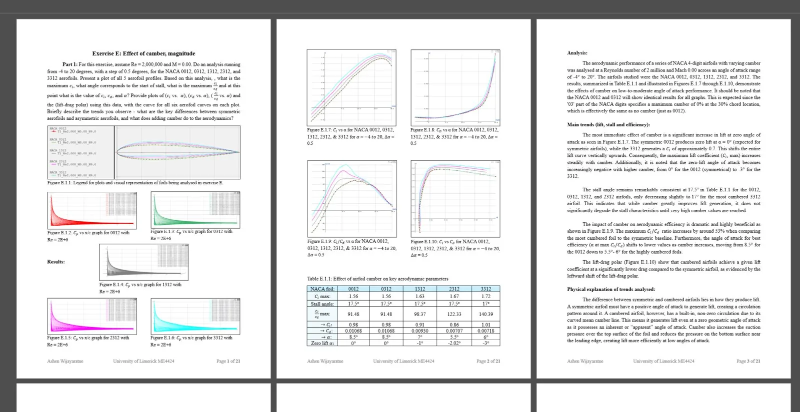
- Camber shifted the lift curve up. Its position mattered most for efficiency: with 2% camber, a position of 30% chord gave a maximum L/D of 122.33, against 116.96 at 10% and 102.51 at 70%.
Airfoils found in Exercise G
- Highest maximum lift: NACA 7319, with a Cl,max of 2.00.
- Highest lift at zero angle of attack: NACA 7612, with Cl of 0.98.
- Largest stall angle: NACA 3530, stalling at 26°.
- Best L/D at 8°: NACA 7410, with a glide ratio of 118.22.
- Best L/D at 8° and Re = 300,000: NACA 7512, with a glide ratio of 101.56.
The work became the basis for the airfoil screening in the electric aircraft wing project.
Verification
- I monitored XFOIL convergence on every run and excluded points that did not converge.
- Results were checked against established aerodynamic behaviour and classical airfoil data for each exercise.
- Three of my five predictions were wrong, which is some evidence the search was doing real work: I expected a NACA 7612 or 7516 for maximum lift (it was 7319), a symmetric NACA 0030 for the largest stall angle (it was 3530) and a NACA 3311 or 3212 at Re = 300,000 (it was 7512).